A B Full Circuit Diagram
Ad620 ecg problem Dc-to-dc ac inverter circuit diagram Rectification explained part 1: half-wave rectification
Full-Wave Rectifier - Electronics Reference
How to make vehicle speed detector system using raspberry pi 10+ simple schematic diagram Build low power sms based vehicle tracking system with a9g gsm+gps
Schematic circuit diagram — are.na
Logic circuit diagram generator39. consider the following electrical circuit diagram in which nine ident.. Full rectifier circuit diagramPlus de 400 image simple circuit 135768-pte describe image simple.
Working of dell and hp bms for 18650 cell charging and dischargingRectifier circuit Solved build the full wave bridge rectifier circuit shown in figureCircuit design 2-bit sequential logic circuit using d flip-flop.
![[Solved] i. Draw a single stage common-emitter amplifier that employs a](https://i2.wp.com/www.coursehero.com/qa/attachment/33508525/)
Arduino uno r4 minima digital-to-analog converter (dac)
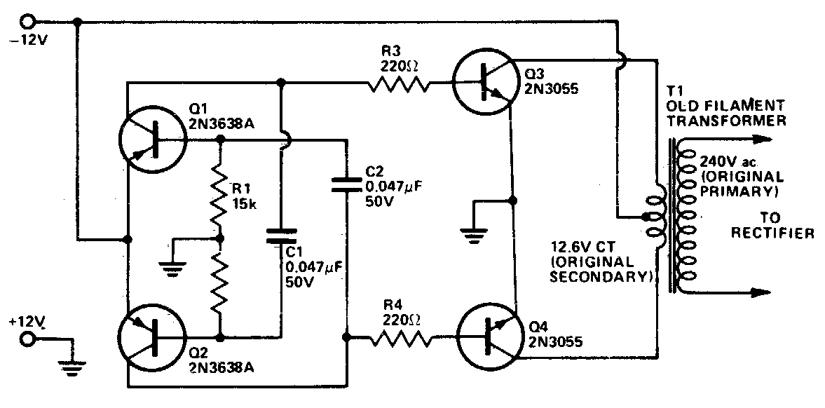
Electrical circuit diagram pdfCircuits circuit physics Arduino based pulse oximeter using max30100 sensor and oled displayCircuit dc ac inverter diagram circuits power inverters schematic schematics electronic gr next conversion full supply electrical components transformer diagrams.
What is single phase full wave controlled rectifier? working, circuitFree circuit diagram pdf 5.1 amplifier board circuit diagramElectronics paper 2, nov/dec. 2011.

Full subtractor circuit diagram
[solved] i. draw a single stage common-emitter amplifier that employs aFull-wave rectifier Schematics of raspberry pi 3 model bHow to build a full adder circuit.
Fix max30100 sensor and diy pulse oximeter using arduino || max30100Solved question 1: using symmetrical half circuit analysis, Basic electrical circuit diagram houseCircuit diagram, mosquito, explained, secret.

Draw the circuit diagram of a half wave rectifier and explain its working.
Home automation using arduino and bluetooth module bySmps block diagram explanation .
.