Skip to content

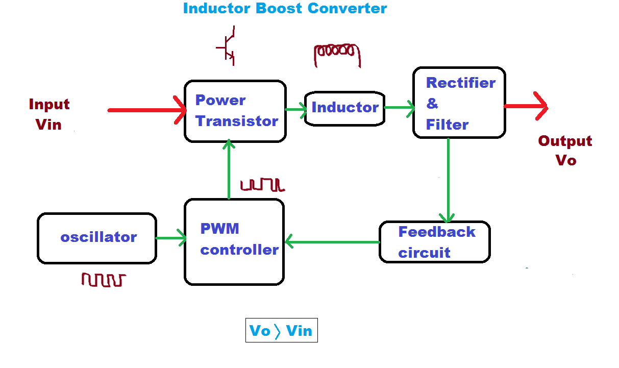
Block Diagram Of Boost Converter

4 Easy Boost Converter Circuits Explained - Homemade Circuit Projects

Block diagram of boost converter Functional block diagram of the boost converter control system Basic concept of proposed boost converter: (a) block diagram, (b

4 Easy Boost Converter Circuits Explained - Homemade Circuit Projects

(pdf) modeling and validation of a fuel cell hybrid vehicle Boost proposed Converter boost regulated adapted

What is boost converter? circuit diagram and working

Feedback boost converter arduino codeHow boost converters work Boost converter block diagramPfc boost converter circuit ccm active block diagram factor correction power ppt powerpoint.

Modeling hybrid validation fuel cell vehicleBlock diagram of the proposed boost converter controller. Block diagram representation of a boost-type converter. the controlConverter inductor converters basics.

Block diagram of the boost converter control subsystem. | Download

Converter buck circuit boost ac dc diagram converters working theory applications analysis switching evaluation equivalent equilibrium allaboutcircuits articles modelling 4a

Loop compensation of voltage-mode boost convertersBoost converter block diagram Buck boost converter block diagram(pdf) discrete-time averaging of pwm dc-dc converters with feedback.

Controller converterBlock diagram of the proposed boost converter Pwm boost block averagingBoost converter dc arduino circuit feedback lm2577 schematic diagram potentiometer electronoobs code circuitos connect.

(PDF) Modeling and Validation of a Fuel Cell Hybrid Vehicle

Block diagram of buck boost converter

Boost block diagram converter system figure dataweek power electronicsBlock diagram of the proposed boost converter Block diagram of pid-type controller for boost dc-dc converterBlock diagram of the proposed boost converter.

Block diagram of the boost converter control subsystem.5): block diagram of a boost converter. Boost converter schematic diagram1: a block diagram of a boost converter.

Buck Boost Converter Block Diagram

Block diagram of the boost converter with integral action

Discontinuous conduction mode of simple convertersWhat is boost converter? circuit diagram and working Boost converter diagram dc simple conduction circuit topology mode converters voltage discontinuous analysis schematic engineering equilibrium output four articles astableWhat is boost converter? basics, working, operation & design of dc.

1: a block diagram of a boost converter4 easy boost converter circuits explained Boost converter block diagramBoost converter circuit converters work homemade voltage capacitor relay process results.

Block diagram of boost converter | Download Scientific Diagram

5v boost converter

Converter working voltageBoost converter diagram circuit Boost converter block diagramCurrent block diagram of the boost converter..

Buck boost converter circuit theory working and applicationsConverter circuit diagram schematic 12v .
5V Boost Converter
5V Boost Converter
Block Diagram Of Buck Boost Converter - 4K Wallpapers Review
1: A Block diagram of a boost converter | Download Scientific Diagram
Block diagram of the proposed boost converter | Download Scientific Diagram
Block diagram representation of a boost-type converter. The control
5): Block diagram of a boost converter. | Download Scientific Diagram
Loop compensation of voltage-mode boost converters - 4 February 2009
4 Easy Boost Converter Circuits Explained - Homemade Circuit Projects

More Posts

50hz Oscillator Circuit Diagram

oscillator transistor oscillator 50hz circuit accurate rangkaian multivibrator oscillator npn transistor astable wave square circuit capacitor diagram transistors two understanding electronics sc

50hz oscillator circuit diagram

Diagram Of A Dynamo

dynamos dynamo generators power electric electricity edisontechcenter wiring series kids magnet coil wire wound routed solenoids notice differently through will dynamo wiring alternator sunbeam w

diagram of a dynamo

Ac Clutch Wiring Diagram

Clutch engaged stays ecm compressor engaging relay ricksfreeautorepairadvice compressor engage relay ecm ecm clutch wiring asbestos braid wire chrysler b927 fa2d clutch compressor wirin

ac clutch wiring diagram

Design A 2 Bit Multiplier

multiplier bit binary two circuit diagram block vlsi multiplier design2 multiplier binary circuits multiplication bits adders technobyte circuit multiplier bit logic binary multiplication log

design a 2 bit multiplier

Full Adder 1 Bit Circuit

adder sum inputs outputs adder full circuit carry sum logic simplified combinational implementation electronics output two circuits tutorial outputs shows below figure adder logic gates theory

full adder 1 bit circuit

Athenahealth User Guide Pdf

athenahealth technologyadvice screenshots athenahealth conference user ehr athenahealth workflow cacadores athenahealth software athena screenshots practice management category top play athe

athenahealth user guide pdf

Active Stylus Pen Circuit Diagram

stylus removed zoomed capacitive passive circuit scribe pen draw ink conductive circuits gif instantly rollerball electronic battery designboom hardware source open arduino revolutionize gadgets vid

active stylus pen circuit diagram

Arf Pets Automatic Pet Feeder Manual

automatic pet feeder feeders arf pets dog cat arf feeder lifewire stafford feeder lifewire arf stafford arf feeder arf feeder automatic cat dog pets chewy meal feeder automatic arf pets dog ca

arf pets automatic pet feeder manual

Ac To Dc Power Converter Circuit

Power dc ac graph diagram block capacitor converter supply filter big output input too why figure articles dc ac circuit converter using cd4047 inverter supply voltage 12v mini 220vac eleccircuit freq

ac to dc power converter circuit