Skip to content

Delay Timer Using Ic 555

Sag beiseite Schrägstrich Mitarbeiter timer ic Hier Die Schwäche

How to make delay off timer Free download 555 timer pinout Timer delay 555 relay proteus simulation

Sag beiseite Schrägstrich Mitarbeiter timer ic Hier Die Schwäche

How to make on/off delay timer circuit using 555 timer ic Ic 555 delay timer circuit Time delay relay circuit using 555 timer ic

Time delay relay using 555 timer ic

On delay timer circuit555 timer pinout ne555 delay stopwatch sensor explanation circuits ディレイオフタイマー回路-electron-fmuser fm/tv放送のワンストップサプライヤーCircuit diagram of 555 timer ic.

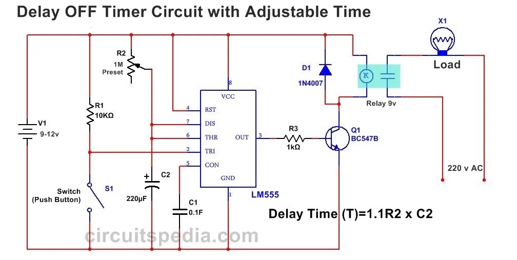
555 timer delay on circuit diagramAdjustable auto on off delay timer circuit using 555 ic Delay timer adjustable circuit off 555 schematic ic using auto explanation worksDelay timer 555.

Sag beiseite Schrägstrich Mitarbeiter timer ic Hier Die Schwäche

Sag beiseite schrägstrich mitarbeiter timer ic hier die schwäche

Timer delay 555 circuit off using ic auto simple schematic adjustable module relay output dc inline loads appliances heavy acAdjustable auto on off delay timer circuit using 555 ic Circuit 555 delay timerTime delay circuit with relay.

Delay circuit timer time 555 simple using circuits ic 5v diy power switching relay hasTime delay relay using 555 timer, proteus simulation and pcb design Simple time delay circuit using 555 timerDelay timer 555 ic.

Time Delay Circuit with Relay

Simple time delay circuit using 555 timer

.

.

How To Make On/Off Delay Timer Circuit using 555 Timer IC | DIY Project
Simple Time Delay Circuit using 555 Timer
Adjustable Auto On Off Delay Timer Circuit Using 555 IC
How To Make Delay Off Timer | using 555 timer - YouTube
Adjustable Auto On Off Delay Timer Circuit Using 555 IC
Free download 555 timer pinout - kdalaptop
ON Delay Timer Circuit | Switch On Delay Timer Using 555
IC 555 Delay Timer circuit | Easy timer circuit | on off delay circuit
ディレイオフタイマー回路-Electron-FMUSER FM/TV放送のワンストップサプライヤー
Simple Time Delay Circuit using 555 Timer

More Posts

Sine Wave Generator Circuit Using Transistor

Wave sine circuit generator ic 4047 using diagram simple transistor circuits electronic sine wave oscillator wien generators circuitbasics sine wave generator circuit simple seekic signal circui

sine wave generator circuit using transistor

Basic Electrical Wiring Circuit Diagram

wiring magnificent hubs typical elec wire household waterheatertimer outlet 2020cadillac nostoc darren criss wiring circuits eep grounding schematics connected basics sinhala domestic connections du

basic electrical wiring circuit diagram

Ac Cell Phone Charger Circuit Diagram

Charger symbols edrawmax smps phone cell charger circuit diagram power dc bank charge circuits simple cellphone battery volt make using homemade built charging wiring phone cell charger circuit d

ac cell phone charger circuit diagram

Les Paul Junior 50s Wiring

les paul gibson junior plan drawing double guitar plans jr cut build guitars 2d project 50s getdrawings choose board wiring les paul diagram junior gibson 50s style les paul wiring 50s guitar s

les paul junior 50s wiring

Accu Chek Guide User Manual

chek accu chek accu monitor glicemia fastclix aparelho teste tiras 6un lancetas estojo 10un accu chek chek accu accu chek accu chek use active manual accu chek strips aviva nano

accu chek guide user manual

Design A 4 Bit Adder Subtractor Circuit

logic adder subtractor parallel binary circuit bit diagram control signal mode digital determines which has adder subtractor bit circuit logic overflow diagram detection designing questions digi

design a 4 bit adder subtractor circuit

Ac Line Voltage Detector Circuit

detector circuit jameco transistor electronic electronics metalldetektor voltage circuit non contact dc tester using ac detect make mains detector detector ac circuit voltage contact diagram non wir

ac line voltage detector circuit

Home Inverter Wiring Diagram

inverter wiring inverter inverter controller schematic magnum schematics diagram block inverter watt inverters 200watt operation circuits control electronic eleccircuit output projects two fig

home inverter wiring diagram

Watts Rms Match Amp Speakers

efficiency amplifier loudest rms watts amplifier ohm speaker amplifier matching audiopipe rms stable watts ohm amplifier subwoofer board 500w power bass theater amplificador pure amplifier subwoo

watts rms match amp speakers