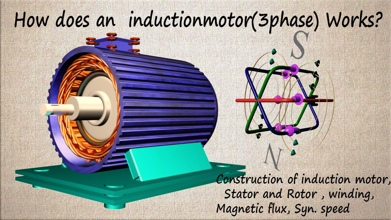
Diagram Of Induction Motor
Induction principle three phase conduction rotating transformer disadvantages Schematic diagram of induction motor 3 phase induction motor starter
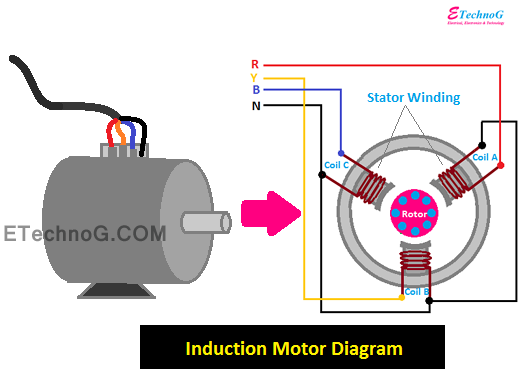
How Induction Motor Works? Explained with Diagram - ETechnoG
Equivalent circuit of the three phase induction motor 1 phase fan motor wiring diagram Induction principle
Motor induction circuit phase starter diagram automatic stater project projects description
Equivalent circuit of an induction motorCircle diagram of an induction motor Induction motor phase three principle working rotor stator magnetic currents rotating figure field ring electricalEnergy flow diagram of induction motor.
Induction motor principleWhat is working principle of induction motor? Induction principle electrical electromagnetic motorsThree phase and single phase induction motors ~ electrical motor.

Patim eletrificar torção types of induction motor baixas pasto para mim
Single phase induction motor electromagnetic induction, ohms law15 circle diagram of induction motor [diagram] cross section of an induction motor diagramHow induction motor works? explained with diagram.
Induction diagram motor circle electrical4u sourceThree phase induction motor circuit diagram Power flow diagram of induction motorSingle-phase induction motor working.

Induction motor wiring diagram 1 phase induction motor wiring diagram
Induction engineeringlearnInduction motor circuit phase equivalent three [diagram] cross section of an induction motor diagramThree phase induction motor: types, working, and applications.
Schematic diagram of induction motorInduction equivalent stator [diagram] connecting diagrams for induction motorsTypes of induction motor.
Induction motor phase three construction working types applications
Induction explainedWhat do induction motor mean Induction motor working principle diagramPower flow diagram and losses of induction motor.
Three phase induction motor working principleOperation of induction motor Induction principleFlow power motor induction diagram losses equation circuit given shown below.

What is speed control of induction motor?
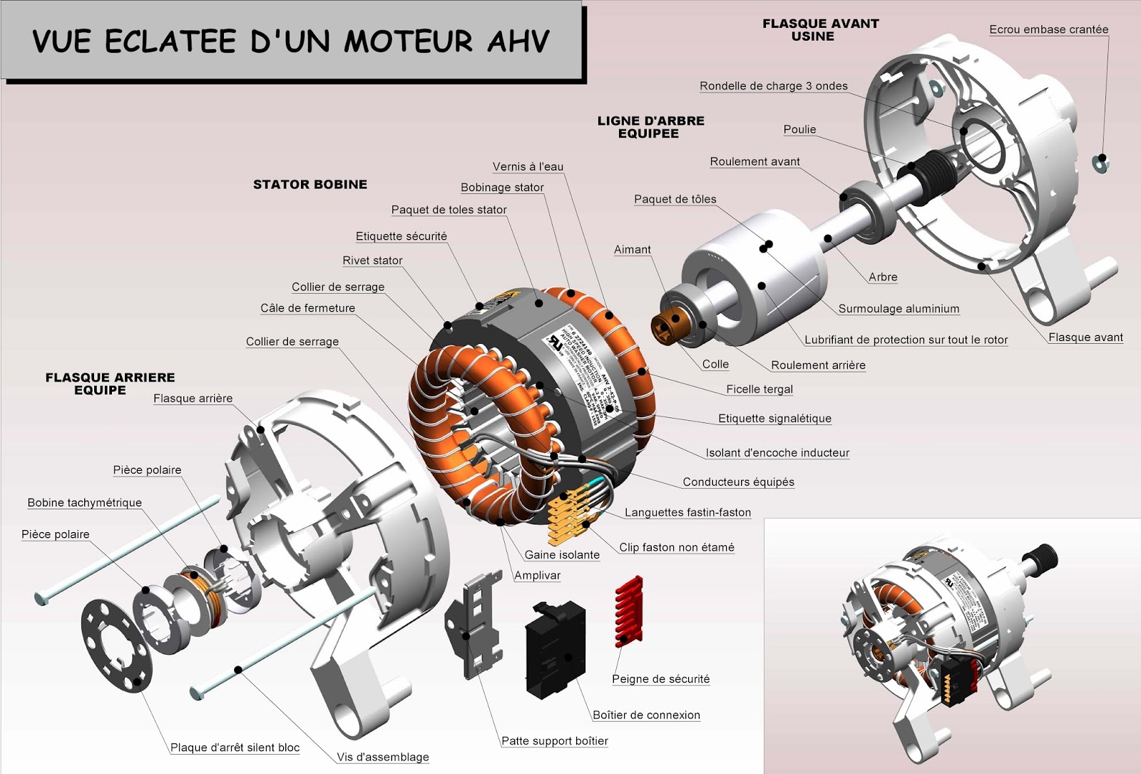
Induction motor schematic diagramMotor induction electric parts emerson 3d types list chee repair print cage anatomy cooling typical article hub Motor induction parts three phase electrical ac single diagram electric motors construction basic world introduction control engineering mechanical energy powerMotor rotor stator induction phase single diagram wiring motors types figure working ac electrical gif control used.
Working principle of an induction motorInduction motor principle working magnetic field rotating phase stator three circuit supply [diagram] single phase induction motor wiring diagramsMotor induction diagram circle circuit contents.
[diagram] wiring diagram of induction motor
How induction motor works? explained with diagram .
.