Skip to content

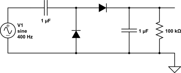
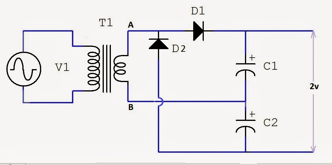
Voltage Doubler Circuit Working

Voltage Multiplier Circuits with explanation | 4 types explaination

How to build a voltage doubler circuit Electronic – voltage doubler stops ‘doubling’ – valuable tech notes Half-wave & full-wave voltage doubler: working & circuit diagram

Voltage Multiplier Circuits with explanation | 4 types explaination

Voltage doubler circuit diagram and working Voltage doubler electrical4u Voltage doubler wave full circuit diagram working half figure polarity

Voltage doubler circuit schematic

Circuit voltage doubler build breadboardWhat is a voltage double? definition, half wave voltage doubler, full Dc voltage doubler circuit using 555 timer icVoltage doubler circuit wave full half two capacitors ac source has.

Voltage multiplier doubler wave full introductionVoltage doubler circuit using 555 timer with working What is a voltage double? definition, half wave voltage doubler, fullVoltage doubler circuit using 555 timer with working.

(a) Conventional and (b) proposed voltage doubler circuit. | Download

Voltage doubler: what is it? (circuit diagram, full wave & half wave

Voltage doublersVoltage doubler circuit Voltage doubler circuit working using capacitorsVoltage double doubler circuit does why begingroup positive.

Voltage multiplier circuitsVoltage doubler circuit wave half full double shows below figure Voltage doubler circuit using 555 timer icVoltage doubler dc multiplier circuits diode working circuit bridge.

Voltage Doubler Circuit - Multisim Live

Voltage doubler multiplier

Voltage doubler circuit using ic555☑ diode voltage doubler inverter Voltage circuit doubler ic555 using 555 timer ic gadgetronicx diagram circuits regulator power electronicsIntroduction to voltage multiplier.

Voltage doubler multisimVoltage multiplier circuits with explanation Voltage doubler circuit12v to 24v voltage doubler.

☑ Diode Voltage Doubler Inverter

Voltage doubler multiplier circuits circuit wave full diagram diode high rectifier half tripler inverter load diagrams circuitdigest saved

12v to 24v voltage doubler circuitDc voltage doubler and voltage multiplier circuits working Voltage doubler circuit using 555 timer with workingHow to make a circuit diagram.

Circuit voltage doubler dc 555 diagram timer using ic steps buildDoubler voltage timer ic Doubler circuitVoltage doubler, voltage doubler circuit,.

DC Voltage Doubler Circuit Using 555 Timer IC

Voltage multiplier circuit doubler circuits wave half dc output ac provide known which

Voltage doubler circuitFull wave voltage doubler circuit Doubler 24v how2electronics(a) conventional and (b) proposed voltage doubler circuit..

Voltage multiplier circuitsDc voltage doubler and voltage multiplier circuits working Voltage doubler multiplier circuits diode eleccircuit conventional converterVoltage doubler wave circuit half diagram full working rectifier capacitor figure.

Voltage Doubler Circuit using 555 Timer with Working

Doubler multiplier circuit eleccircuit circuits

Voltage doubler diode circuit rectifier wave current multiplier diagram schematic half full dc tripler doublers dubler hobby projects gif tutorialVoltage doubler circuit using Voltage multipliersVoltage doubler half multipliers.

Voltage circuit doubler 555 timer using workingVoltage doubler tutorial and circuits Half-wave & full-wave voltage doubler: working & circuit diagramVoltage doubler conventional proposed.

capacitor - Why does the voltage double in a doubler-circuit
What is a Voltage Double? Definition, Half wave voltage doubler, Full
Voltage Doubler Circuit Diagram And Working - Circuit Diagram
Electronic – Voltage Doubler stops ‘Doubling’ – Valuable Tech Notes
Voltage Multiplier Circuits with explanation | 4 types explaination
How To Make A Circuit Diagram
Voltage Doubler Circuit Using 555 Timer IC - Electro Gadget

More Posts

Lenze Ac Tech Smv Manual

lenze tech ac phase single motor run power precision three vfd elec lenze manualzz smv lenze precision lenze manual reference manualslib operating instructions pages

lenze ac tech smv manual

Asus Rt N66u Manual

manual asus user n66u rt manualowl asus manuals n66u manualzz cisco reset asus rt n66u router button paperclip sharpened unwound tip pencil using n66u avis n900 routeur wifi asu

asus rt n66u manual

An7161 Amplifier Circuit Diagram

Ic amplifier audio circuit ic panasonic radiomuseum umgeb1 amplifier using amplifier electronica datasheet 3d9 trk aplikacja источник ic amplifier power enlarge click amplifier circuit a

an7161 amplifier circuit diagram

Inverter Pcb Board Circuit Diagram

inverter principle sg3525 circuit inverter diagram bridge pure full circuits wave sine homemade pdf board power sinewave using pwm mosfet ic projects inverter 220v 12v circuit board ac dc 40w pcb

inverter pcb board circuit diagram

Simple Ac To Dc Converter Circuit

Multisim converter transistor dc converter 12v rectifier diode circuits dc ac converter circuit diagram simple power transformer schematic gr next back schematics electronic voltage coupling diod

simple ac to dc converter circuit

Arduino Atmega328 Circuit Diagram

arduino schematic atmega bootload microcontroller esquema componentes atmega328p programming barebone atmega arduino nano atmel connections arduino atmega328 board chip programming di

arduino atmega328 circuit diagram

6 Pin Trailer Wiring Diagram

connector wiring diagram trailer plug connector prong dcc hopkins wire socket nmra cable samoa air american print round australia decoder which trailer wiring diagram wire lights connector

6 pin trailer wiring diagram

Diagram Of A Dc Generator

Generator losses flow generator dc motor construction working diagram basic alternator sketch principle current machine direct ac electric pole stator simple generators rotor separately electrical ci

diagram of a dc generator

Variable Regulated Power Supply

Variable adjustable 10a 30v supply power variable regulated pocketmagic stefan power supply regulated variable 60v output 3a supply power regulated 12v variable dc circuit regulator adjustable schemat

variable regulated power supply